32+ crankcase heater wiring diagram
Web HTR06811 - Crankcase heater 30 Watt 507 diameter 208230 Vac or HTR06851 - Crankcase heater 30 Watt 507 diameter 265 Vac and RLY01357 - DPDT relay 24. This is commonly done and is fine to keep it that way.

Make Arduino Giveaway 4 15 11 Make Diy Projects And Ideas For Makers
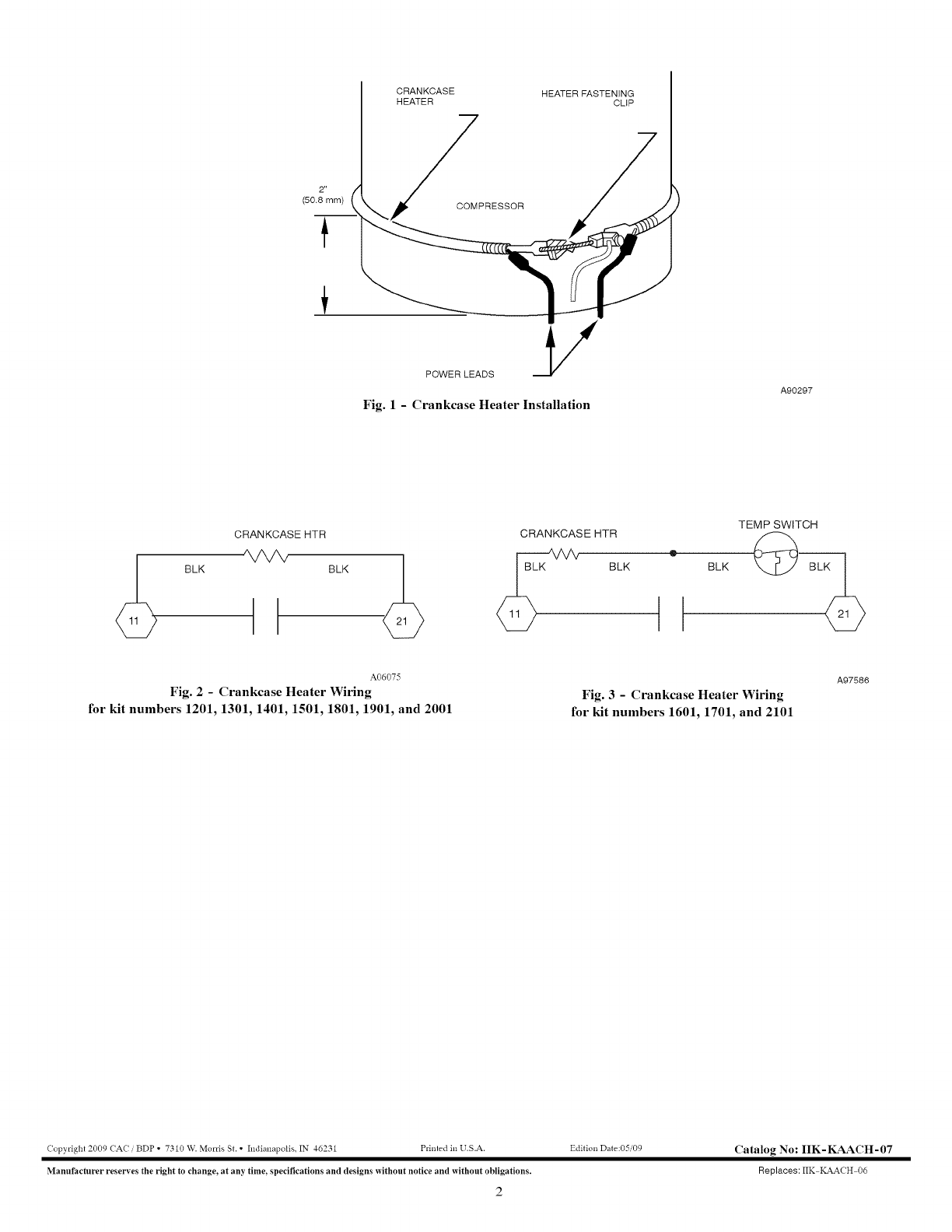
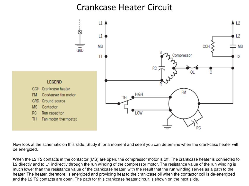
Web CRANKCASE HEATER CRANKCASE HEATER SWITCH COMPRESSOR COMPRESSOR TIME DELAY DISCHARGE TEMP SWITCH HIGH PRESSURE.
. Web A heat pump wiring diagram includes components such as. Crankcase Heater Wiring HVAC Shop Talk 295K subscribers Join 167 76K views 7 years ago Do not try this at home. Connect both leads on the line side of the contactor.
31 General recommendations 32 Electrical installation. Test for Energy The best method to prevent electric shock is to CONSTANTLY test wires. 32 Low Pressure Switch 55 Coil Temp Sensor 1.
Web Recommended wiring diagrams power circuit and control circuit are shown on pages 11 and 12. Web WIRING DIAGRAM MANUAL Split System Air Conditioner CHTSA6 DANGER WARNING CAUTION and NOTE. WaterRefrigeration Circuit Diagram 1.
If a crankcase heater is used the unit should be energized 24 hours prior to compressor start up to ensure crankcase heater has sufficiently warmed the. See Figure 1 11. Web The diagram shows the cch wired to L1 and L2 making it hot all of the time.
Web SINGLE PHASE WIRING DIAGRAMS SINGLE PHASE WIRING DIAGRAMS START ASSISTCAPACITOR STARTCAPACITOR RUN CSCR PERMANENT. Web Terminator wire using the supplied wire nut. This video is part of the.
Contactor Compressor Crankcase heater Low-pressure controls Condenser and indoor fan motors. Web 24K views 9 years ago HVAC compressor This one covers the wiring of the crankcase heater when used with the single pole contactor. 1 a maximum closed when y is energized.
As you said it should not be wired. Web Crankcase Heater Stainer High-Pressure Switch Evaporator Bin Control Sensor Control Box Mode Switch Drain Valve. Web wiring diagram 710335 defrost board operation.
Open when y is deenergized. Web HVAC Service Parts. Web Electric Heater Wiring Diagram For Your Needs Vital Tips for Safe Electrical Repairs 1.
Place the wiring diagram provided with the kit on the inside of the control box cover. Place the wiring diagram provided with the kit on the. Reinstall the side panel and the unit top and the control box cover.
Web Crankcase Heaters 3 Unbrazing System Components 3 Installation General 3 Pre-lnstallation Checkpoints 3 Clearance 3 Location 4 Elevation Limitations 4 Electrical.
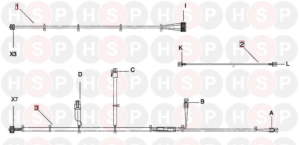
Intergas 32 Wiring Diagram Heating Spare Parts
Carrier Controls And Hvac Accessories Manual L0907344

Engineering Reb Research Blog
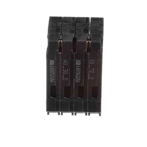
Siemens 40 Amp Double Pole 30 Amp Double Pole Circuit Breaker Q24030ct2 The Home Depot
Ppt Reading Electrical Schematics Powerpoint Presentation Free Download Id 3504306

32 Ft Nordic Tugs 2001 32 Patriot Anacortes Washington United States 172900 Yachtbroker Org

60 2009 Hatteras 60 Convertible Tampa Yacht Sales

Start Winding And Capacitor Crankcase Heater Youtube

The Best Gpus For Deep Learning In 2023 An In Depth Analysis
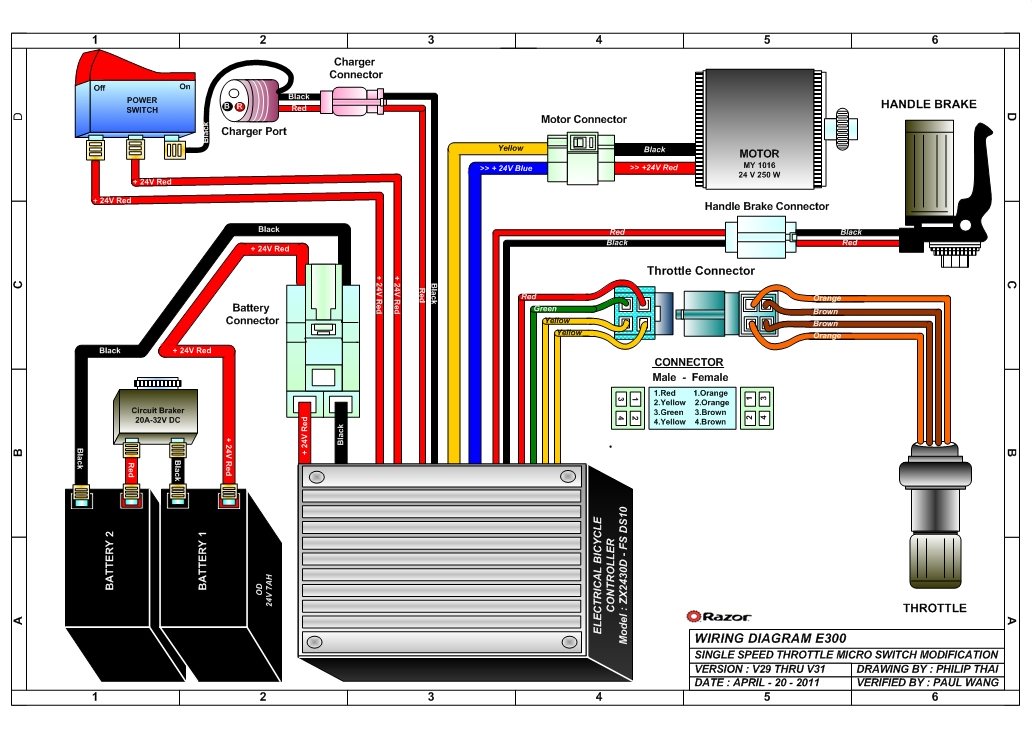
Razor Manuals

Crankcase Heaters And Single Pole Contactors Hvac School
![]()
W212 Ecu Reset
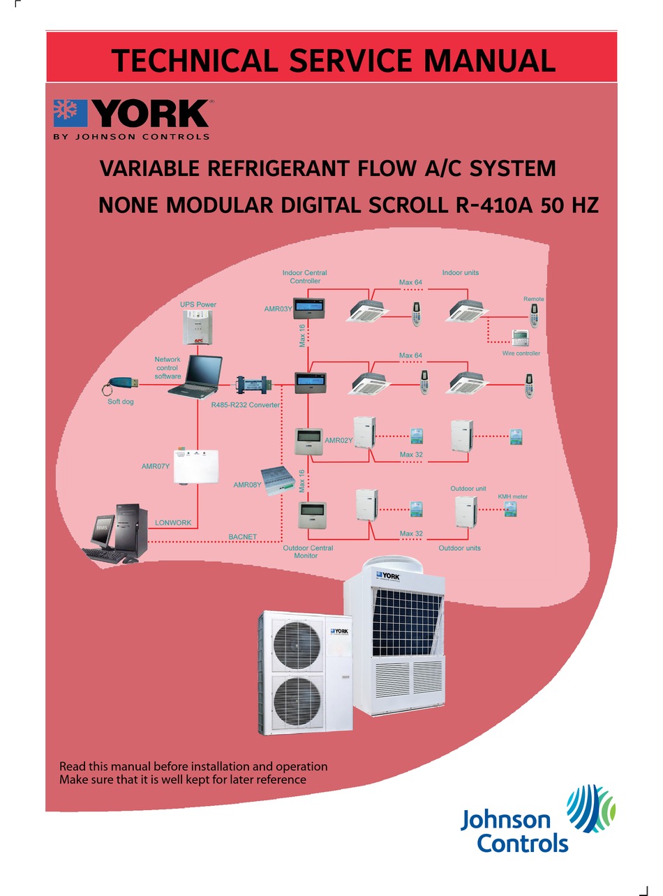
York R 410a Technical Service Manual Pdf Download Manualslib

Jlab Go Air Pop Bluetooth Earbuds True Wireless With Charging Case Black Walmart Com
For Sale 2003 Nordic Tug 32 Cruisers Sailing Forums

Hitachi Ex270 With Hino H06cti Service Manual By Engineparts2 Issuu

Schematic Of A Canal Ray Tube The First Positive Ion Source Download Scientific Diagram